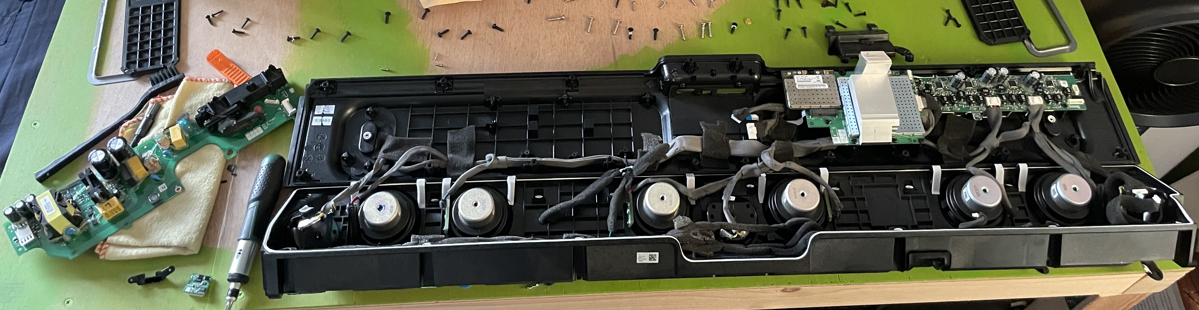
Fixing a Sonos Playbar: Coil Whine and a Dead Toslink Receiver
I picked up a second-hand Sonos Playbar for €65. It was listed as defective, the toslink shutter was broken and the seller mentioned a faint noise. What followed was several weeks of board-level debugging, frequency analysis, nail polish, and three (three!) toslink receivers. This is the full story.
The Setup
The Playbar had two known issues when I bought it:
- A high-pitched whine coming from the power supply
- No toslink input (broken shutter, possibly more)
I started with the coil whine because it was audible and measurable. The toslink I assumed would be a simple connector swap.
I was wrong about the second one.
Part 1: Diagnosing the Coil Whine
First Suspicion: Capacitors
Coil whine that develops over time often points to degraded capacitors in the SMPS control circuit: a dying cap causes the switching frequency to become unstable, which makes the transformer sing. I replaced the bulk electrolytic caps first.
The whine remained.
Frequency Analysis
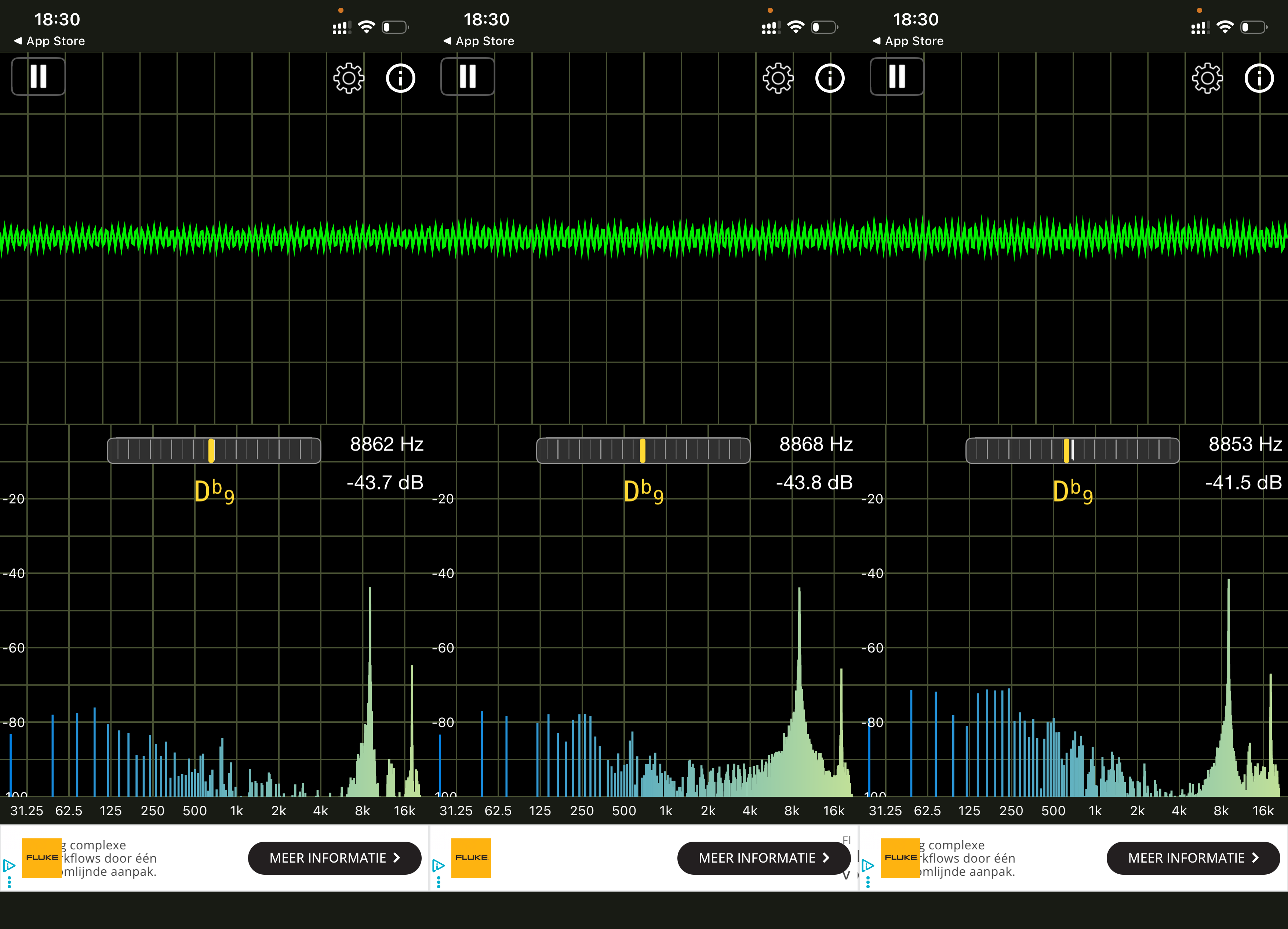
I used a spectrum analyzer app on my phone (microphone held close to the open Playbar) to get actual measurements. The dominant peak was consistent around 8.8 kHz, which is right in the audible range and typical for a switching power supply.
I took measurements near the main transformer and near the MOSFETs separately:
Near the transformer (coil):
| Measurement | Frequency | Level |
|---|---|---|
| 1 | 8862 Hz | -43.7 dB |
| 2 | 8868 Hz | -43.8 dB |
| 3 | 8853 Hz | -41.5 dB |
Near the MOSFETs:
| Measurement | Frequency | Level |
|---|---|---|
| 1 | 8834 Hz | -52.0 dB |
| 2 | 8942 Hz | -52.5 dB |
| 3 | 6917 Hz | -69.4 dB (frequency shifted, load change) |
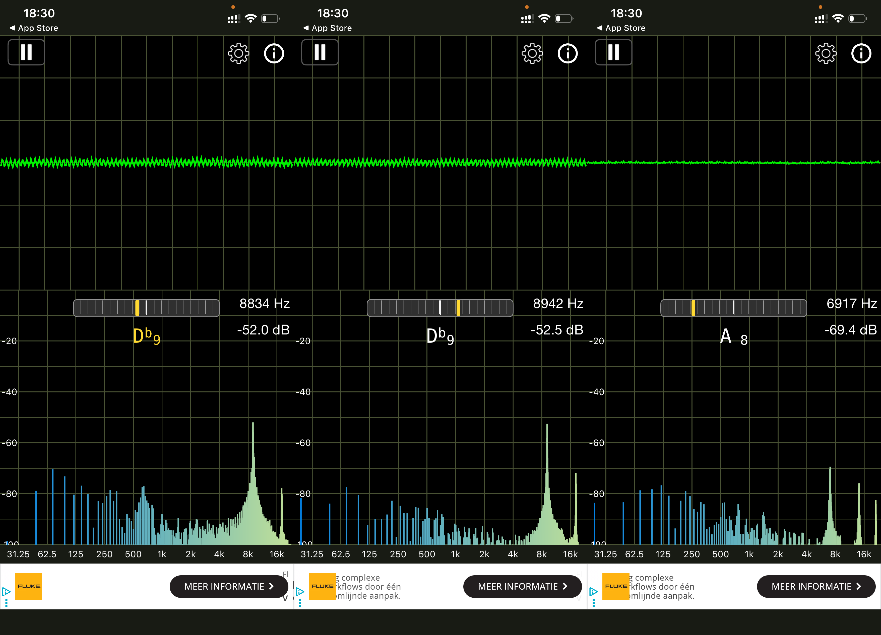
Conclusion: The transformer was 8–10 dB louder than the MOSFETs at the same frequency. The coil was the source. The sudden frequency shift to 6917 Hz in the third MOSFET measurement confirmed a variable-frequency SMPS responding to load changes in the Playbar, witch is normal behavior.
Identifying the Transformer
The main transformer is an EE/EF-type ferrite core transformer: two black ferrite E-halves clamped together with plastic clips around a yellow Mylar-wrapped bobbin. Part number on the label: DXTPQ3230-161, dated 2013/5/16. Given the date, I was not surprised about it having coil whine.
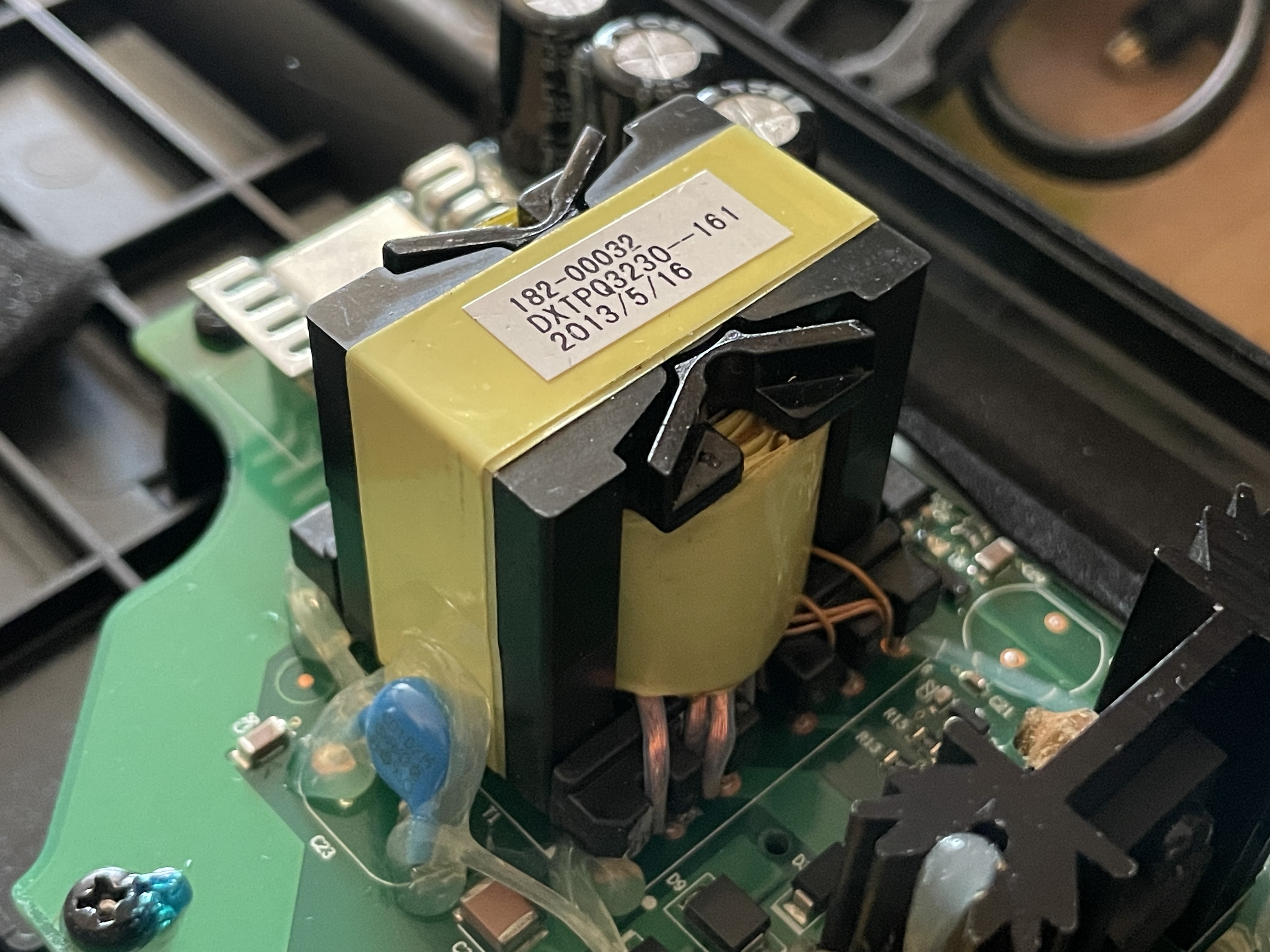
The magnetostrictive vibration of the ferrite core halves against each other, held only by plastic clips, not bonded, is the classic cause of this type of whine.
Part 2: The Fix with Nail Polish
The standard repair for transformer whine is mechanically damping the core halves. Options range from proper coil potting compound to conformal coating. I had access to neither.
What I did have: a trip to the Etos drugstore.
Why Nail Polish Works
Nail polish is nitrocellulose lacquer. It’s thin enough to wick into gaps via capillary action, and it dries rigid, which shifts the resonant frequency of the winding assembly and reduces vibration amplitude. It’s been used for exactly this purpose for decades.
Important notes on this approach:
- Thermal: Nail polish adds insulation. Check the transformer temperature before applying. If it runs above ~60°C, be conservative with coverage.
- Solvent safety: Acetone/ethyl acetate vapors are heavier than air and pool in enclosed spaces. Work with the unit open and ventilated.
- Mylar compatibility: PET (Mylar) is chemically resistant to nail polish solvents. The existing insulation is safe.
What I Used
Plain, non-gel, non-glitter transparent nail polish from the drugstore. Base coat formula, thinner and more fluid than top coat, better capillary action.
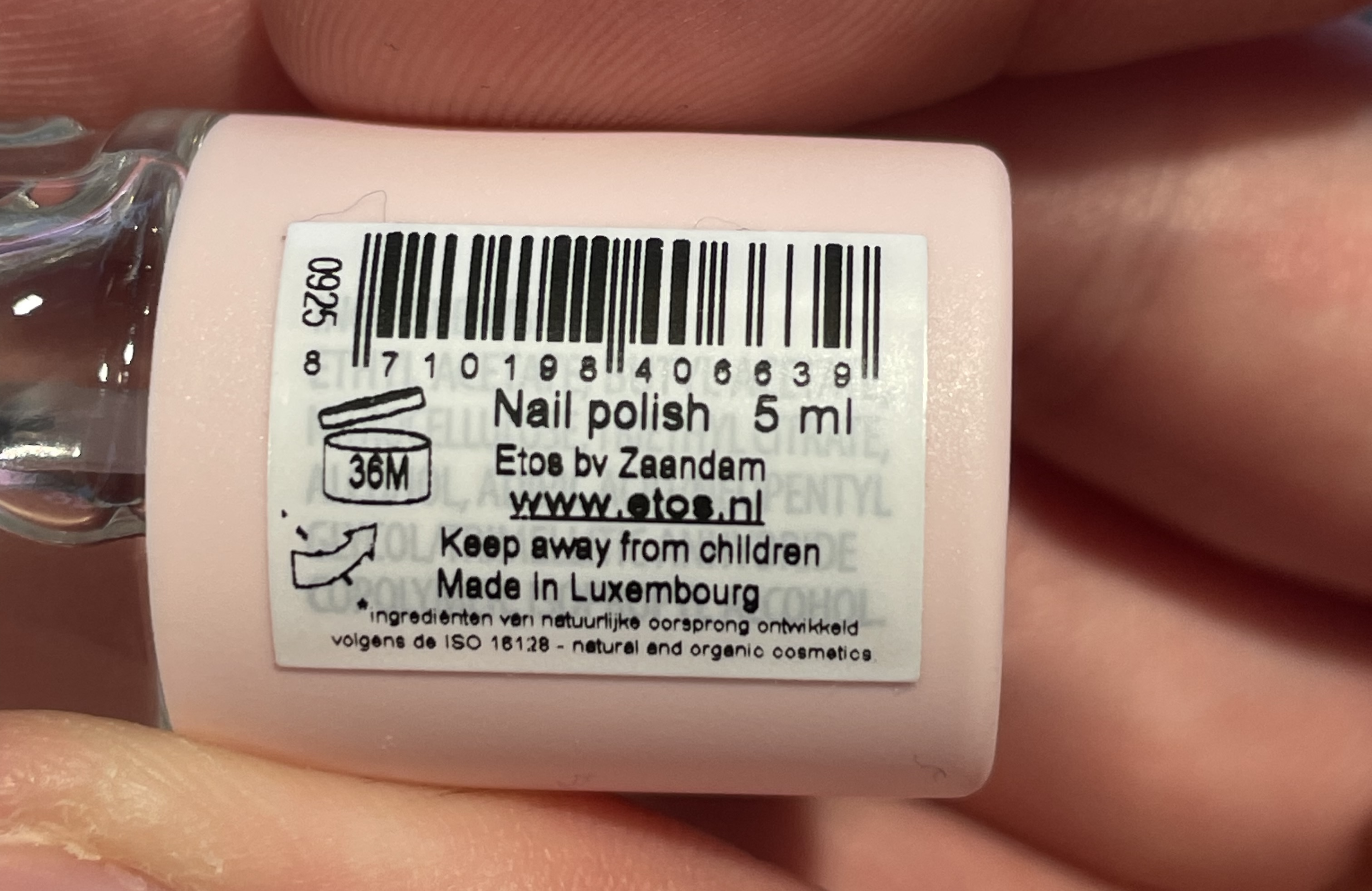
Application
With the board powered off and capacitors discharged (2+ minutes wait, then verified with a multimeter):
- Applied a thin coat along the seam where the two ferrite halves meet, running horizontally. (Red)
- Let dry 10 minutes between coats.
- Also applied a thin coat ** between the ferrite and the bobbin**, where black meets yellow. (Blue)
- Wait 10 minutes again before applying the next coat.
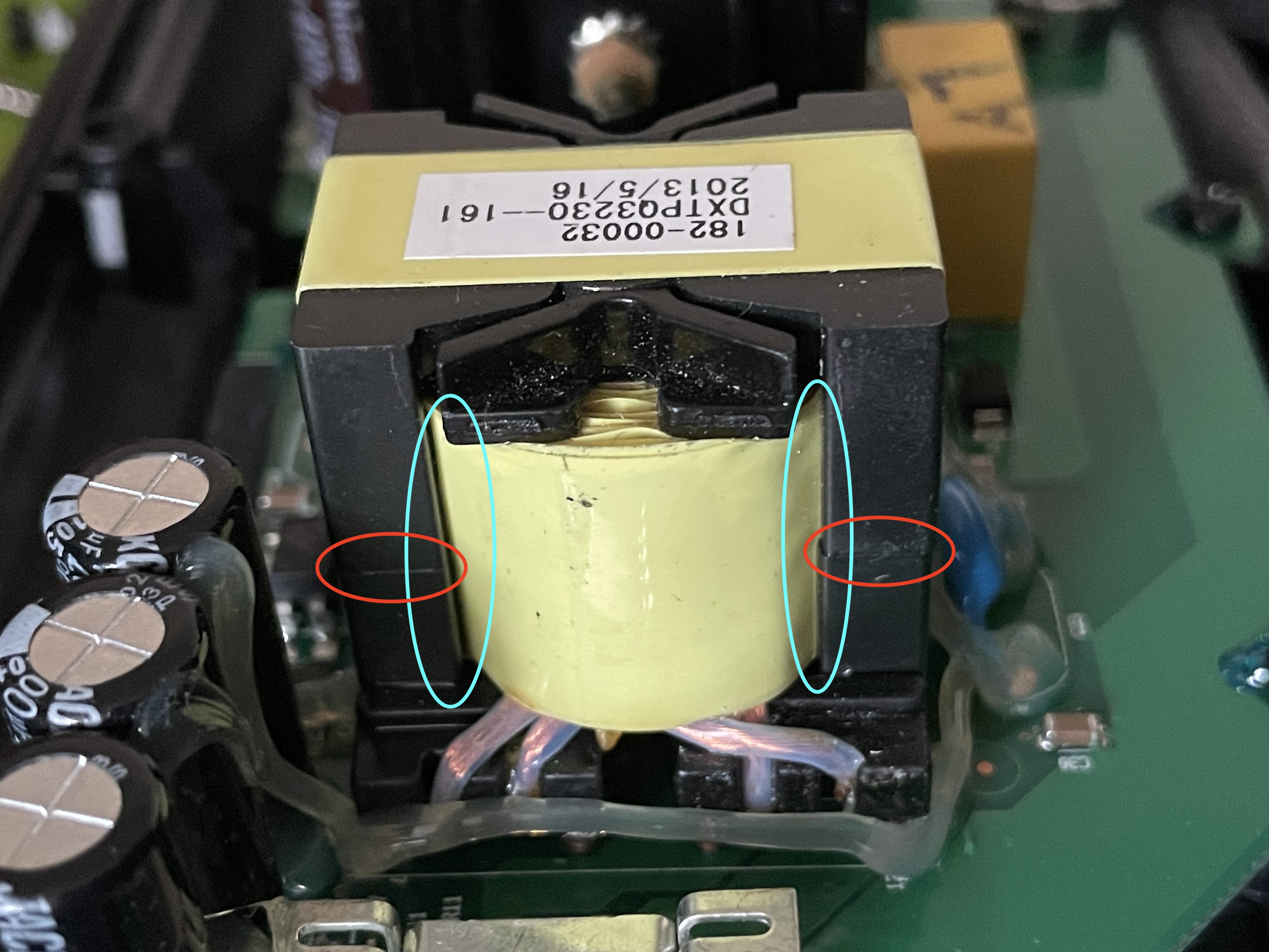
I did three coats total on both places, applied over two sessions. Make sure to do all sides for 1 (red) and both front and back for 3 (blue).
Results
The improvement was measurable and progressive:
| Stage | Frequency | Level |
|---|---|---|
| Baseline | 8.8 kHz | -41 dB |
| After coat 1 | 13.4 kHz | -54 dB |
| After coat 2 | 13.6 kHz | -65 to -68 dB |
| After coat 3 | 13.6 kHz | -60 to -74 dB |
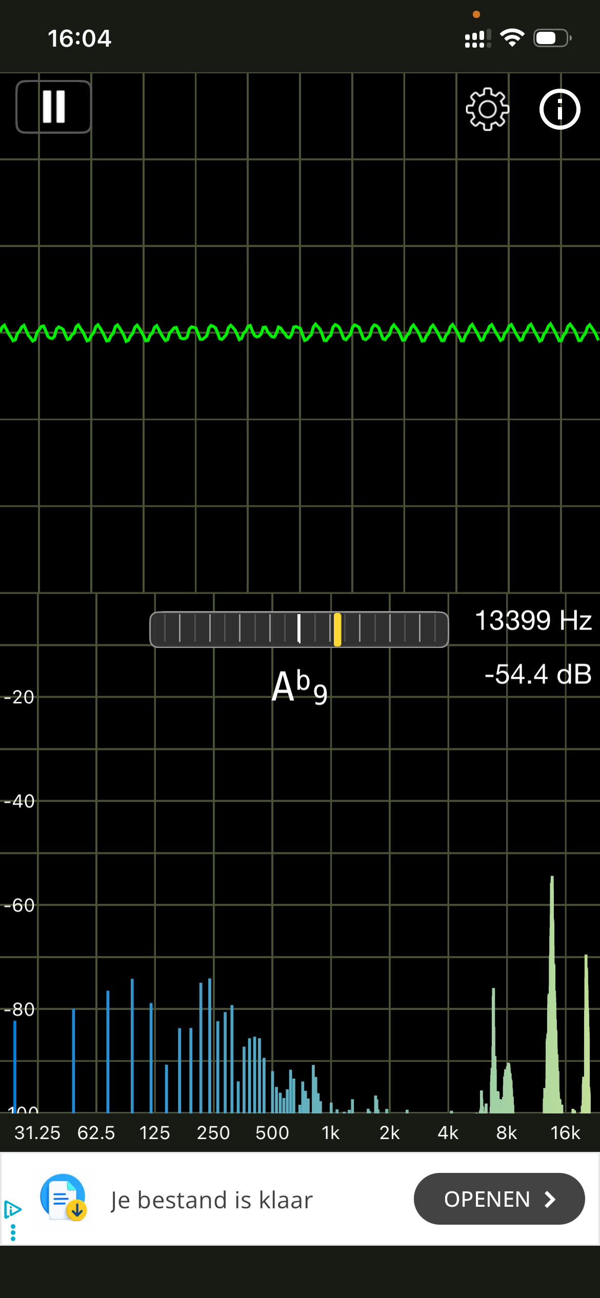
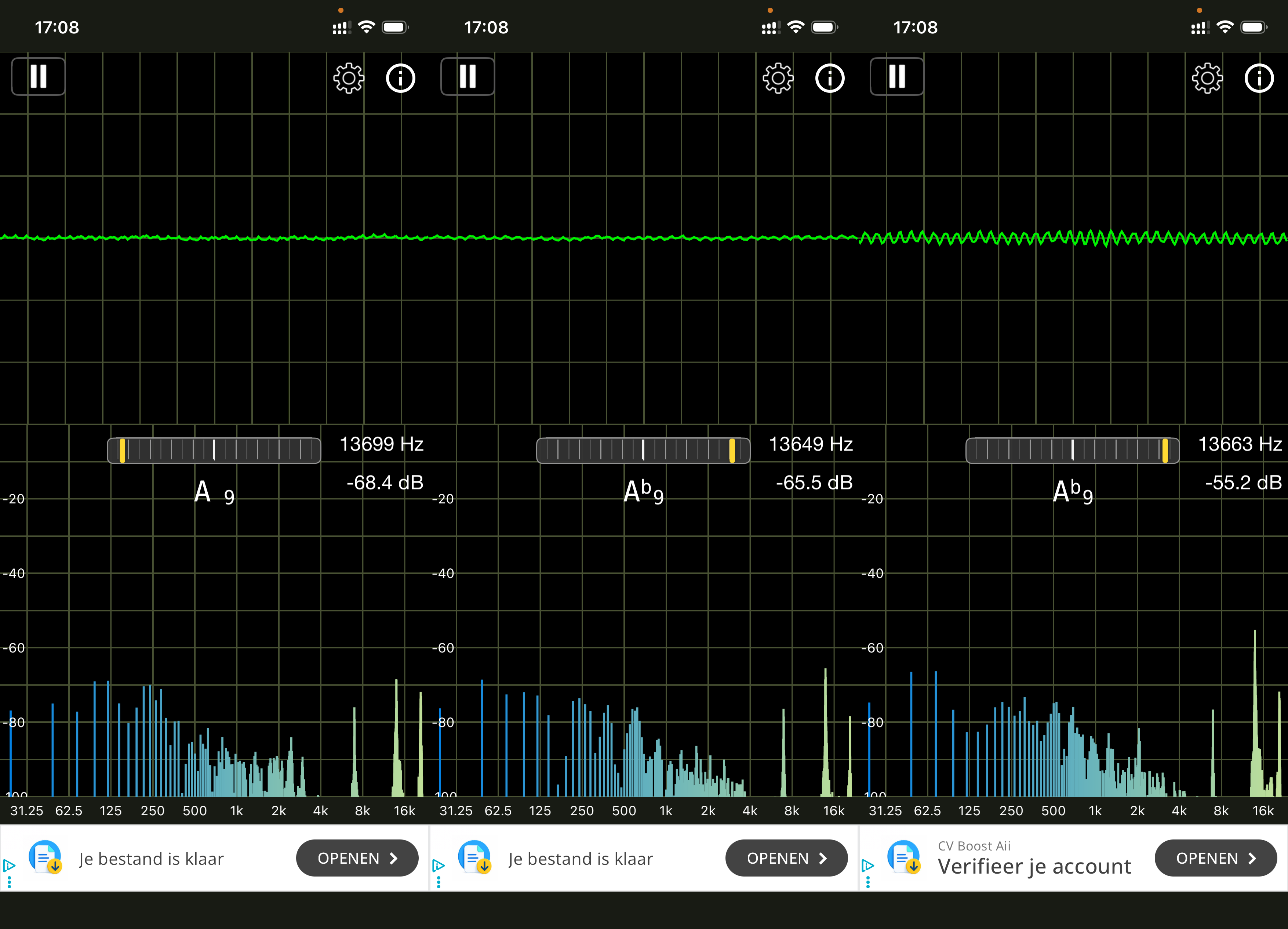
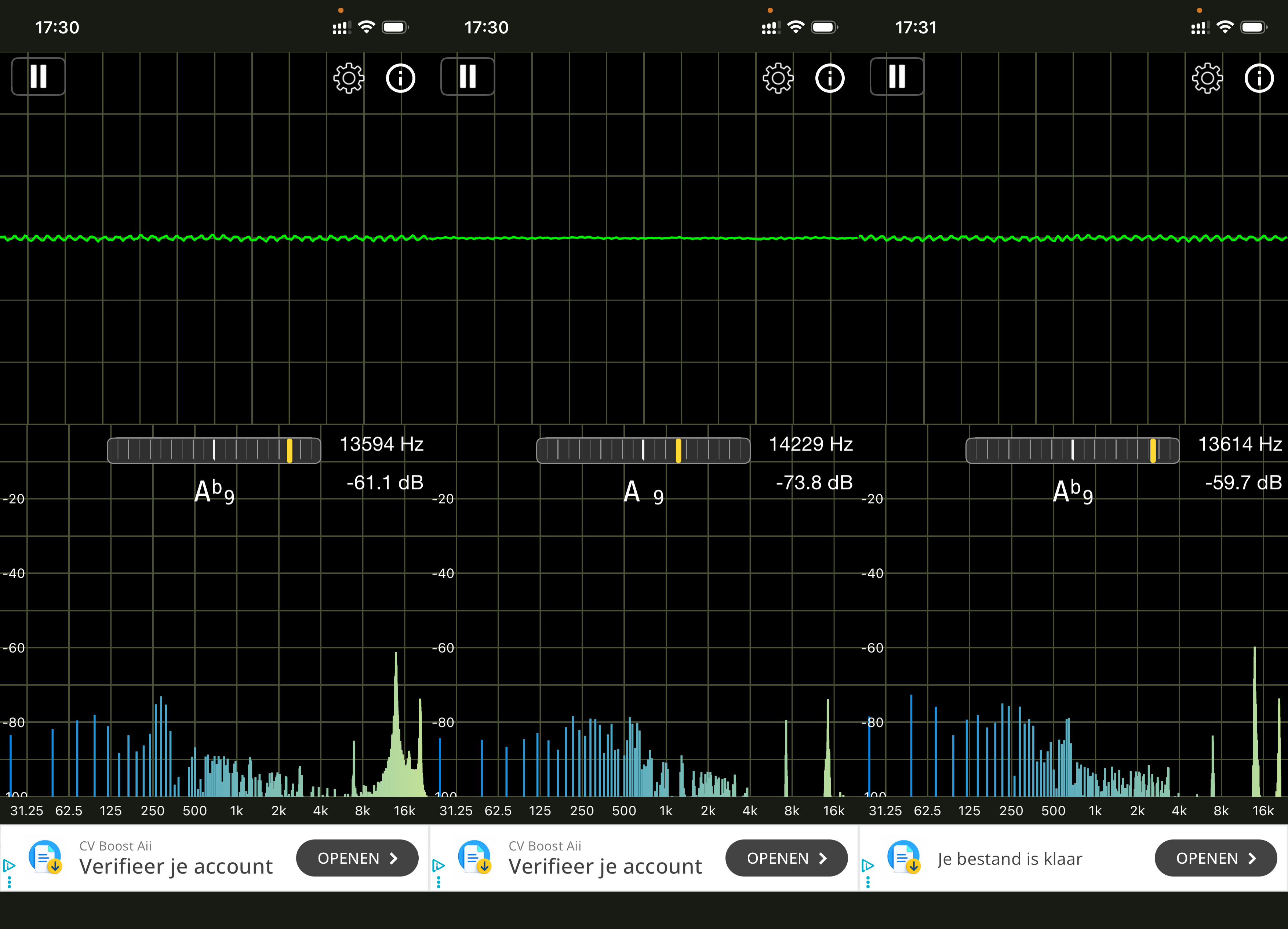
Two things happened: the frequency shifted upward (from 8.8 kHz to ~13.6 kHz, harder to hear), and the level dropped by 25–30 dB. The end result was that the whine fell below the amplifier noise floor, audible only when the amp is idle and you’re listening for it at close range with the unit open. With the case closed, it’s gone.
Part 3: The Toslink Rabbit Hole
With the whine fixed, I turned to the toslink input. The shutter (the little flap that covers the optical port) was broken, so I ordered a replacement toslink receiver: FCR684208R from Cliff Electronic Components, sourced via Farnell.
Receiver 1: Dead (my fault)
I desoldered the old receiver and installed the new one. No detection. I assumed I had overheated it. I had no solder wick, which meant holding each joint hot longer than ideal.
Receiver 2: Also dead (probably also my fault)
Ordered a second. Better technique this time, but still some trouble with a middle pin and some stray solder. Same result: no detection, no signal.
Receiver 3: Actually good soldering this time
Ordered a third, along with proper solder wick. Used a different iron running cooler, faster-melting solder, never more than 3–4 seconds per joint. The datasheet specifies max 260°C / 5 seconds / 2 times maximum. I stayed well within that.
Same result. Still no detection.
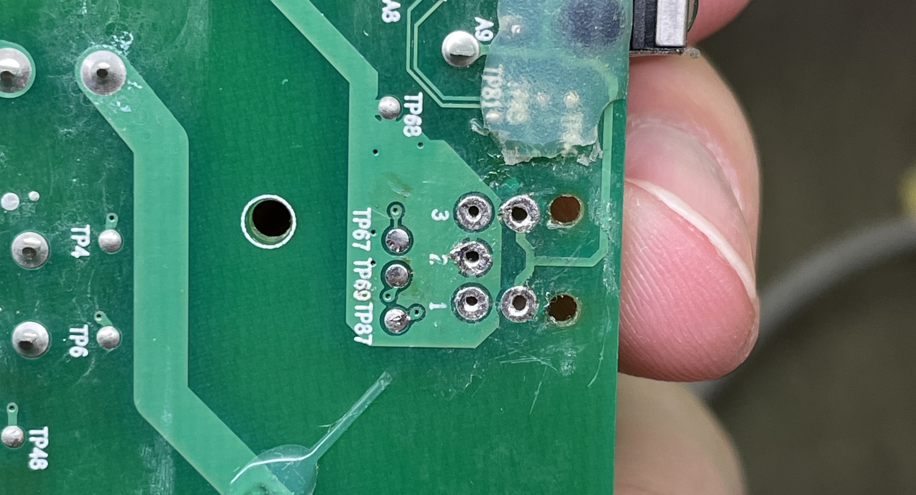
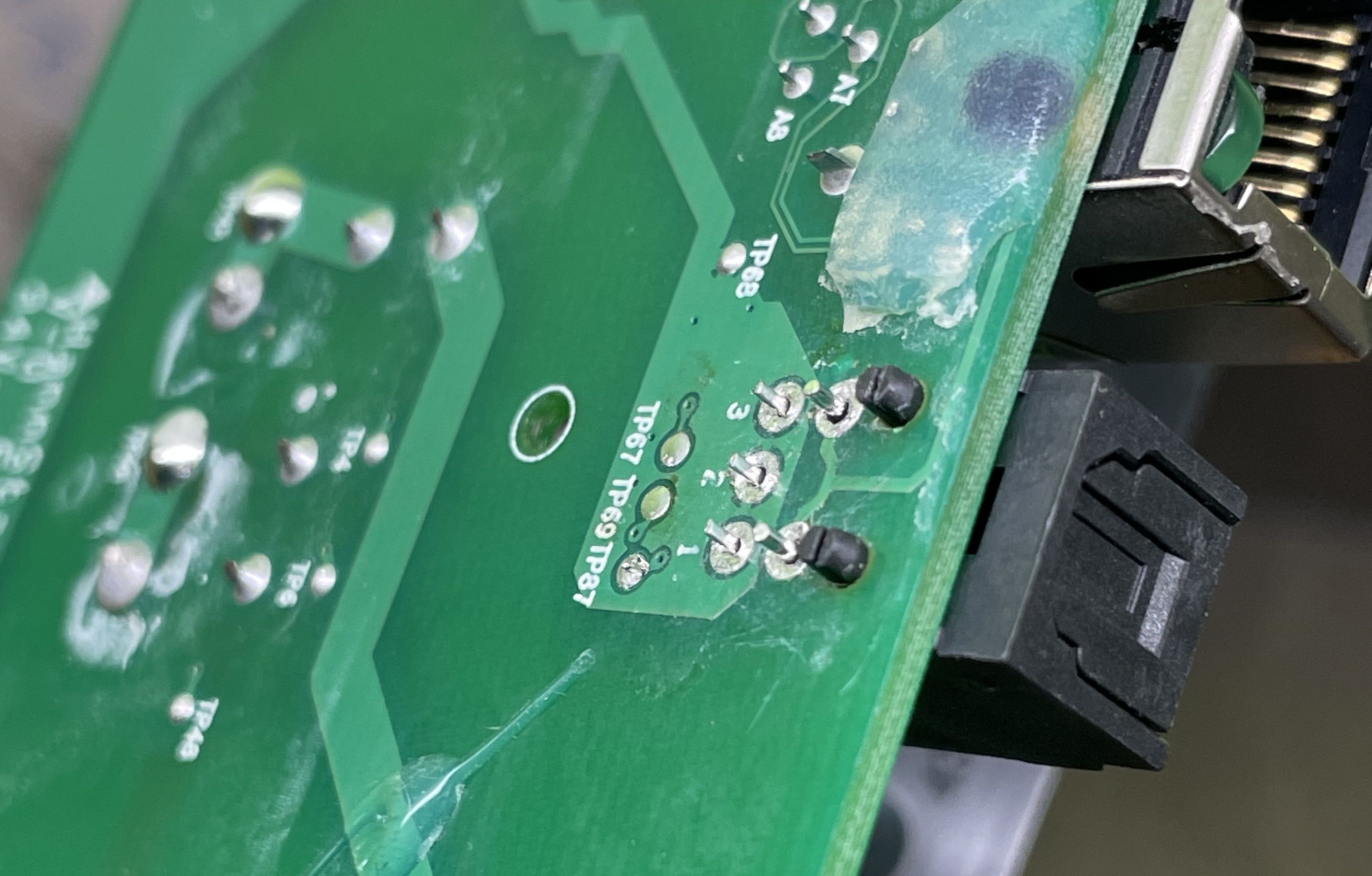
Note: Make sure you remove the glue and clean the solder holes well, so that the toslink connector can click into place before you solder, like shown below, before you start soldering.
Board-Level Investigation
At this point I suspected the problem wasn’t the receiver at all. I checked:
- Solder joints on the transformer (looking for dry joints causing intermittent behavior): all clean and shiny
- Bottom of the board: good condition, no obvious damage
Then I tested the ribbon cable connecting the toslink board to the main board, 10 pins, all lanes had continuity. Ribbon was fine.
Voltage Measurements on the Toslink Circuit
With the board installed and powered:
!!!Warning!!! Be careful, stay away from the 230V side.
| Test point | Condition | Reading |
|---|---|---|
| TP67 to TP68 (Vcc to GND) | Always | ~3V DC |
| TP87 to TP68 (Vout to GND) | No input | 0V |
| TP87 to TP68 (Vout to GND) | Active toslink input | 1.67V DC |
| Pin 1 to Pin 2 directly on receiver | Active input | 1.67V DC |
The 1.67V on Vout with an active signal is consistent with a fast-switching digital signal (SPDIF) being averaged by a multimeter. A working receiver switches between 0V and Vcc at megabit speeds, and the meter sees the average. It’s not a perfect measurement but it suggests the receiver is alive.
The receiver was getting power. The receiver was outputting something. The problem was downstream.
Resolution
After all of this, I tried the simplest option. I used a different toslink cable and source from a friend of mine.
The Playbar immediately detected the optical input and worked perfectly fine, so my initial goal of fixing the Playbar was achieved.
Three receivers, a voltage probe session, a ribbon cable continuity check, a Sonos community and Reddit post (See Links at the bottom), and it just wasn’t the Playbar.
Lesson: always try a second cable and source, before assuming the hardware is broken.
Bonus: The Source Issue
After digging a little deeper, I found that the cable I had was also working, after trying a bit harder in the settings of a TV I had. This meant the real culprit was the Analoge to Digital Converter that I bought for my setup was the problem. I contacted the seller Allekabels, they sent me another one to test to see if my unit was defective, but the seccond one also didn’t work. I contacted them again, we tried all possible settings in the Sonos app and on my MacBook, but with no result.
Eventually we got the idea of trying a different model Converter. And for some unexplainable reason, it worked like a charm when plugging it in. I ended up with this converter.
Summary
| Problem | Root cause | Fix | Cost |
|---|---|---|---|
| Coil whine | Ferrite transformer core vibrating | Nail polish on seam, 3 coats | ~€2 |
| Toslink no signal | Incompatible converter (after receiver replacement) | Different model | ~€0 (had one) |
| Toslink receiver | Overheated ×2 during repair | Replaced ×3 with proper technique | ~€50 in parts and shipping |
The Playbar cost €65. Total spend including all parts, shipping from the UK, and replacement tools: over €115. Not realy defensible given the time and stress, but in the end, technically very satisfying.
Shoutouts
Two thank-yous before I wrap up.
Sonos Support were real bros. I showed up with a 13-year-old device that’s long past End Of Life, has no warranty, was literally lying in pieces, and had been soldered on by me. Tho in the end not needed, they still wanted to try their best, by offering to help and check the diagnostics they could get on their end. Respect.
Allekabels were at least as good. Digging deeper, the real culprit turned out to be the optical transmitter feeding the toslink, not the Playbar. The first converter model I used simply didn’t work, they sent a replacement that also didn’t work, so we tried a different model and it worked instantly. Their technical support, service, and willingness to think along were sublime. I’m never worried that something won’t work when I order from them, even here, where I only noticed the problem long after purchase because I assumed the fault was in the Playbar.
Tools Used
- Spectrum analyzer app (iOS) for frequency measurement
- Multimeter for voltage and continuity
- Soldering iron + solder wick
- Transparent nail polish (base coat, non-gel)
- Fine brush for application
- A lot of patience